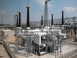
High Voltage Direct Current (HVDC) power transmission systems are often equipped with large ground electrodes at terminal ends of the transmission line in order to offer an alternative earth return path during emergency conditions or routine maintenance on one of the HVDC line pole. Information on the soil structure and its electrical properties within a radius and a depth of tens of km of the HVDC electrode site is required in order to determine accurately the performance of the HVDC ground electrode and its impact on neighboring facilities such as pipelines and power lines. Furthermore, detailed soil resistivity information up to depths on the order of the electrode dimensions is also needed to ensure that step and touch voltages at and around the site are within the safe limits. Electrical and electromagnetic based resistivity profiling methods are useful tools to meet the requirements of characterizing accurately the soil model around the HVDC electrode.
The MultiGroundZ or MultiFields software packages are recommended for HVDC substation and ground electrode design.
This package is suitable for grounding systems of any size. It accounts for the impedance of the conductors making up the grounding system and allows currents to be injected into the system at any number of locations, thus accounting for the effects of circulating currents. It does not, however, model overhead conductors, nor account for inductive or capacitive coupling effects between conductors. However, it does allow the user to specify induced emf values in any conductors, but these emf values must be computed separately. Furthermore, overhead grounding conductors (such as shield wires) can be represented as insulated, buried conductors. In addition to the standard results expected of a grounding package, this package also computes current and scalar potential distribution throughout the grounding system or systems (you may model as many as you wish in a given simulation).


